


 English
 Español
 عربى
عربى
Common Causes of Mooring Line Failure Explained
Content
- 1 Fatigue: The Silent Accumulator of Damage
- 2 Snap Loading: The Single Most Violent Failure Mechanism
- 3 Corrosion and Degradation of Wire Rope and Chain
- 4 Abrasion and Mechanical Damage at Fairleads and Seabed Contact Points
- 5 Improper Tensioning: Too Tight and Too Loose Are Both Dangerous
- 6 Inadequate Inspection and Deferred Maintenance
- 7 Design and Installation Errors That Create Inherent Vulnerability
- 8 Environmental Extremes Beyond Design Basis
- 9 Material Selection Errors and Supply Chain Quality Issues
- 10 Connector and Hardware Failures: The Weakest Links
- 11 Operational Causes: Human Factors and Procedural Failures
- 12 Creep in Synthetic Lines: Slow Failure Under Sustained Load
- 13 What the Failure Data Shows Across the Industry
- 14 Practical Measures That Directly Reduce Failure Risk
Mooring line failure is one of the most consequential events in offshore and marine operations. The primary causes include material fatigue, improper tensioning, abrasion, corrosion, snap loading, and inadequate inspection regimes. Understanding each of these failure mechanisms in detail is essential for vessel operators, port engineers, and offshore installation managers who cannot afford the consequences of an uncontrolled breakaway — consequences that range from cargo loss and structural damage to environmental disasters and loss of life.
This article examines the full spectrum of mooring line failure causes, backed by incident data, engineering principles, and field observations. Whether you are managing a floating production storage and offloading unit (FPSO), a bulk carrier at a berth, or a semi-submersible drilling rig, the failure mechanisms discussed here apply across mooring configurations.
Fatigue: The Silent Accumulator of Damage
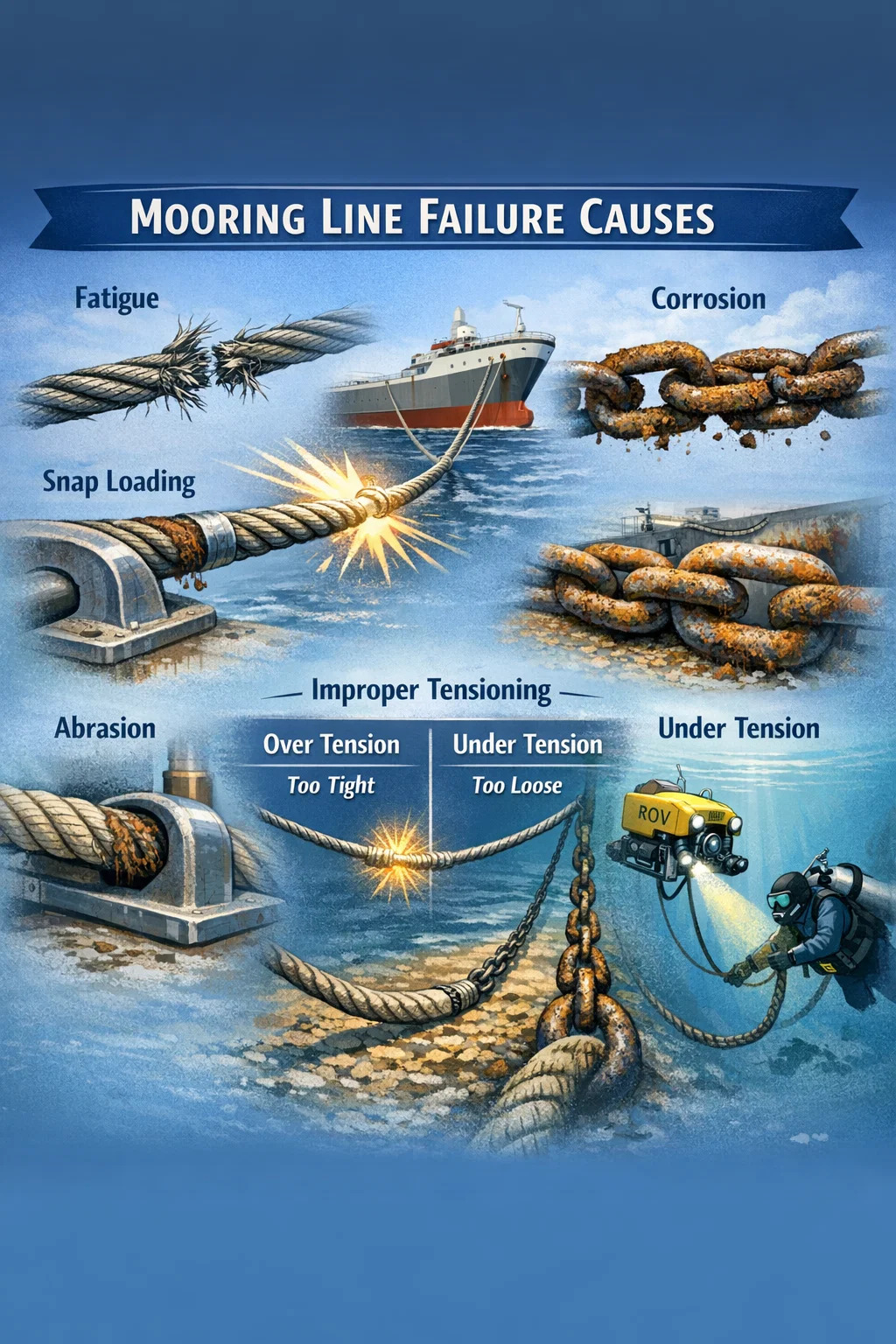
Fatigue is responsible for a disproportionate share of mooring line failures, particularly in offshore environments where lines are subject to continuous cyclic loading from waves, current, and vessel motion. Unlike a sudden overload failure, fatigue damage accumulates invisibly over thousands or millions of load cycles, until a crack propagates through a wire strand or synthetic fiber bundle and the line parts without warning.
In wire rope mooring lines, fatigue manifests as broken wires in the outer strands. Industry guidance from DNV and API RP 2SK indicates that a wire rope mooring line can experience fatigue failure after accumulating damage equivalent to just 10–20% of its nominal breaking load applied cyclically over millions of cycles, a threshold far lower than most operators intuitively expect. For synthetic lines — polyester, HMPE, or nylon — fatigue damage appears as fiber creep, internal abrasion between yarns, and progressive stiffness change.
The fatigue life of a mooring line is heavily influenced by the tension range (the difference between minimum and maximum load in a cycle), the mean tension, and the frequency of loading. Lines subjected to a high tension range at elevated mean loads consume their fatigue life much faster. In harsh offshore environments such as the North Sea or the Gulf of Mexico during hurricane season, a mooring line can accumulate years' worth of fatigue damage in a matter of weeks.
Key Fatigue Drivers to Monitor
- High sea states that generate large vessel excursions
- Resonant vessel motions aligned with dominant wave frequencies
- Low pretension leading to slack-taut cycling (see snap loading below)
- Improper catenary geometry that concentrates bending at fairleads
- Extended operational life beyond original design assumptions
Snap Loading: The Single Most Violent Failure Mechanism
Snap loading occurs when a mooring line goes slack and then is suddenly jerked taut by vessel motion. The dynamic load imposed during the snap can be two to ten times the static break load of the line, making it the single most destructive force a mooring system can experience. Lines that survive years of normal cyclic loading can part instantly during a single snap-load event.
Synthetic lines — particularly nylon, which has high elongation — are especially vulnerable because they store and release energy elastically. When a slack nylon line snaps taut, the energy release is instantaneous and the resulting shock load can exceed the line's minimum breaking load (MBL) by a wide margin. The 2004 investigation into the breakaway of the tanker Bow Rora at Milford Haven identified snap loading as the proximate failure mechanism, with a single line parting under an estimated load of 3.2 times its rated MBL during a storm surge.
Snap loading is most likely to occur when:
- A vessel surges excessively in beam or quartering seas
- Mooring lines are overtensioned so catenary support is lost
- Lines are arranged at unfavorable angles to the primary excitation direction
- Vessel loading condition changes dramatically, altering freeboard and line geometry
- Tidal range causes lines to go slack at high water
Corrosion and Degradation of Wire Rope and Chain
Steel mooring components — wire rope, chain, and connecting hardware — are in permanent contact with one of the most corrosive environments on earth. Seawater, combined with cyclic mechanical stress, drives both general corrosion and stress corrosion cracking (SCC). Studies on recovered offshore mooring chains have shown cross-sectional area reductions of up to 30% in the splash zone after 10–15 years of service, even in nominally well-maintained systems.
The splash zone — the region of a mooring line that alternately wets and dries with wave action — is the most aggressive corrosion environment because it combines full oxygen availability with repeated wetting and drying cycles. Chain links in this region can lose 2–4 mm of diameter per decade, which translates directly into reduced MBL since chain strength is proportional to the square of wire diameter.
Corrosion Failure Pathways
- General corrosion: Uniform metal loss reducing cross-section and load capacity
- Pitting corrosion: Localized deep pits that act as stress concentrators under cyclic load
- Stress corrosion cracking: Cracks driven by the combination of tensile stress and corrosive environment, particularly in high-strength steels
- Crevice corrosion: Accelerated attack in the narrow gaps between wire strands or chain link contact points
- Hydrogen embrittlement: Absorption of atomic hydrogen generated by cathodic protection or corrosion reactions, leading to brittle fracture in high-strength steel
Hydrogen embrittlement deserves special attention because it is counterintuitive — it can occur in systems that are correctly cathodically protected. Overprotection (more negative than -1,100 mV vs Ag/AgCl) generates excessive atomic hydrogen at the steel surface, which diffuses into the metal and reduces fracture toughness. Several FPSO mooring chain failures in the 2000s were attributed to hydrogen embrittlement combined with stress corrosion cracking.
Abrasion and Mechanical Damage at Fairleads and Seabed Contact Points
Mooring lines experience concentrated mechanical wear wherever they pass over or through a fixed structure. Fairleads, chocks, bitts, and the seabed contact zone are all locations where abrasion progressively removes material from the line's outer surface, exposing the inner load-bearing components to direct environmental attack.
For wire rope, abrasion at fairleads flattens the outer wires, increasing contact stress and accelerating fatigue crack initiation. Wire rope mooring lines can lose up to 15% of their breaking strength from fairlead-induced abrasion before any visible external damage is detectable, because the worst damage occurs on the underside of the rope where it contacts the fairlead surface.
For synthetic fiber lines, abrasion is equally serious. Polyester and HMPE lines that run over rough fairlead edges or corroded steel surfaces accumulate external fiber breakage that is clearly visible during inspection. However, internal abrasion — fiber-on-fiber wear inside the rope core — is invisible without destructive testing and can reduce strength by 20–40% with no external sign.
At the seabed, chain and wire rope in the touchdown zone are subject to abrasion against coral, rock, or rough sediment. This is compounded by the fact that the touchdown zone shifts with vessel motion and tidal variation, meaning a long section of the line experiences repeated dragging across the seabed surface.
Improper Tensioning: Too Tight and Too Loose Are Both Dangerous
The pretension applied to a mooring line at the time of deployment has a profound effect on its subsequent performance and failure risk. Both overtensioning and undertensioning create failure pathways, through different mechanisms.
Overtensioning
When a mooring line is tensioned beyond its design pretension, the catenary geometry flattens. This has two consequences. First, the restoring force per unit vessel displacement increases dramatically, meaning the system becomes stiffer and transmits larger dynamic loads from vessel motion into the line. Second, the line loses its catenary buffer — the ability to absorb wave-frequency excitation through changes in catenary shape rather than direct line stretch. A line tensioned to 50% of MBL as pretension has approximately one-third the fatigue life of a line tensioned to the design value of 25% MBL, because it operates at a higher mean tension and experiences larger load ranges.
Undertensioning
Undertensioned lines allow excessive vessel excursions, increasing the risk of snap loading as described earlier. They also allow the line to sag onto the seabed over a longer touchdown distance, increasing abrasion exposure. In multi-leg mooring systems, if some lines are slack while others are tight, the tight lines carry a disproportionate share of the environmental load and will fail earlier than predicted by symmetric design analyses.
Tensioning errors are common at installation because winch load cell calibration drift, friction in fairleads, and the difference between static and dynamic conditions all introduce uncertainty. A 2015 study of FPSO mooring integrity found that more than 60% of inspected mooring legs had pretension values outside the design tolerance band of ±15% at the time of inspection, with roughly equal numbers being over and under the target.
Inadequate Inspection and Deferred Maintenance
A mooring line failure that could have been prevented by timely inspection and replacement is arguably the most avoidable kind. Yet deferred maintenance remains a leading contributor to mooring incidents worldwide. The economics of offshore operations create pressure to extend line service lives beyond what engineering analysis would recommend, especially during periods of low oil prices when asset integrity budgets face cuts.
The challenge is that subsea mooring inspection is genuinely difficult. Chain and wire in deep water cannot be directly observed without ROV deployment, and even ROV visual inspection has limitations — it cannot detect internal corrosion, fatigue cracks below the surface, or the residual strength of a corroded chain link. Acoustic and electromagnetic inspection techniques have improved but remain expensive and require interpretation expertise.
Analysis of mooring incidents reported to the International Association of Oil and Gas Producers (IOGP) between 2001 and 2020 shows that approximately 35% of single mooring line failures and over 50% of multiple simultaneous line failures occurred on systems that had not been inspected within the recommended interval. This correlation does not prove causation — a system can fail despite recent inspection — but it clearly indicates that inspection gaps are associated with elevated failure rates.
Common Inspection Gaps
- Failure to conduct underwater inspection of the chain and wire segments
- Visual-only inspection that misses subsurface fatigue cracks
- No measurement of chain link diameter to quantify corrosion loss
- Absence of tension monitoring instrumentation
- Irregular inspection intervals that skip storm-season post-event surveys
- Poor records that make it impossible to track cumulative damage history
Design and Installation Errors That Create Inherent Vulnerability
Some mooring line failures trace back to errors made before the system ever enters service. Design errors include incorrect environmental load assumptions, inadequate safety factors for fatigue, poor selection of line materials for the specific environment, and failure to account for progressive failure dynamics (what happens when one line in a multi-leg system fails and the remaining lines must carry redistributed loads).
Progressive failure is a particularly dangerous scenario. When one line in a symmetric 12-leg turret mooring fails, the load on adjacent lines increases by approximately 20–30% depending on configuration. If those lines are already close to their design limit, the failure can propagate rapidly, turning a single-line failure event into a catastrophic full breakaway. This cascade mechanism was implicated in the 2017 loss of mooring by an FPSO off West Africa, where what began as a single chain failure resulted in the loss of three additional lines within 90 minutes.
Installation errors are equally consequential. Incorrect anchor embedment depth, wrong chain grade installed in a segment, reversed shackle orientation at connectors, insufficient anti-rotation measures on wire rope, and failure to properly proof-load the system before handover have all contributed to documented mooring failures.
Environmental Extremes Beyond Design Basis
Mooring systems are designed to withstand a defined set of environmental conditions, typically expressed as a return period load — for example, a 100-year storm in the Gulf of Mexico. When actual conditions exceed the design basis, the probability of failure rises sharply. The relationship between load and failure probability in a mooring system is highly nonlinear: a 20% increase in wave height may produce a 200–300% increase in mooring line load due to the nonlinear dynamics of catenary geometry and drag forces.
Climate variability and the potential for shifting storm intensity distributions mean that systems designed 20–30 years ago against historical metocean data may now face conditions that exceed their original design assumptions. Hurricane Ivan in 2004 generated waves in the Gulf of Mexico that exceeded the 100-year return period at multiple locations, and resulted in mooring failures at seven separate floating production facilities, a density of concurrent failures that had not been anticipated in any operator's risk model.
Beyond storm loading, other environmental factors can degrade mooring system performance:
- Vortex-induced motions (VIM): Alternating vortex shedding from a vessel's hull in strong currents creates transverse oscillations that generate severe cyclic mooring loads not always captured in frequency-domain fatigue analyses
- Swell in sheltered locations: Long-period swell can penetrate into normally calm bays and ports, exciting vessel resonance at frequencies for which the mooring system has little damping
- Seabed instability: Sediment mobility, submarine slides, or seabed scour around anchor foundations can change anchor holding capacity or mooring geometry
- Fouling: Marine growth on chain and wire increases hydrodynamic drag loads and adds weight, altering catenary geometry and line tension
Material Selection Errors and Supply Chain Quality Issues
The choice of mooring line material has major implications for failure mode and service life. Different materials have fundamentally different strengths, weaknesses, and failure characteristics, and selecting the wrong material for an application — or using a correctly specified material that was produced to substandard quality — can create a latent failure waiting to happen.
| Material | Primary Strength | Main Failure Vulnerability | Typical Service Life |
|---|---|---|---|
| Studless chain (R4/R5) | Abrasion resistance, high MBL | Corrosion, fatigue at welds | 15–25 years |
| Spiral strand wire | High axial stiffness, low drag | Internal corrosion, bending fatigue | 15–20 years |
| Polyester rope | Weight, flexibility, fatigue life | UV degradation, abrasion, creep | 20–30 years |
| HMPE rope | Very high strength-to-weight ratio | Creep under sustained load, thermal sensitivity | 10–20 years |
| Nylon rope | High elongation, snap load absorption | Hydrolysis, UV degradation, snap failure | 5–10 years (harbor use) |
Supply chain quality is a growing concern, particularly for chain. Counterfeit or subgrade mooring chain — chain sold as a high-grade alloy but actually produced from lower-grade steel — has been identified in offshore markets. A 2019 investigation in Singapore found that approximately 8% of sampled mooring chain supplied to regional operators failed to meet the stated grade specification, with some samples having MBL values 25–40% below the certified figure. Hardness testing and chemical analysis at the point of receipt is the only reliable way to catch such substitutions.
Connector and Hardware Failures: The Weakest Links
Shackles, swivels, connecting links, and fairlead pins are the mechanical interfaces of a mooring system. They are typically rated to the same MBL as the line segments they connect, but they are also points of stress concentration, wear, and corrosion. Hardware failures, though less frequent than line failures, are disproportionately severe because they tend to be sudden and complete rather than progressive.
Shackle pin loss is a documented failure mode. If a shackle pin is not properly moused (secured with wire or a cotter pin), vessel motion and line rotation can cause the pin to unscrew over time. Once the pin backs out sufficiently, the shackle opens and the mooring leg is lost entirely. This failure mode is entirely preventable through correct assembly practice but continues to occur due to assembly errors and inadequate verification inspections.
Swivel failure is another concern in rotating mooring systems. A swivel that seizes and stops rotating forces the lines it connects to carry torsional loads they were not designed for, accelerating fatigue. Swivel bearings that corrode and seize are common in systems where the swivel is not regularly inspected and lubricated — maintenance that is difficult to perform in a subsea environment.
Operational Causes: Human Factors and Procedural Failures
Not all mooring failures have their origins in physics or material science. Human decisions and operational errors account for a significant fraction of incidents, particularly in port and terminal mooring where vessel operators and mooring masters make real-time judgments under time and commercial pressure.
Common human-factor failure contributors include:
- Failure to deploy sufficient lines: Using fewer lines than the berth plan requires to save time, with each remaining line carrying an elevated share of the load
- Mixing line types: Combining nylon and polyester or wire and synthetic lines in the same configuration creates an uneven stiffness distribution, causing the stiffer lines to attract disproportionate load
- Failure to tighten lines after cargo operations: As a vessel loads or discharges cargo, its freeboard and trim change, and lines that were properly tensioned at the start may become slack or overstressed as the operation progresses
- Ignoring weather forecasts: Continuing operations or remaining at a berth when deteriorating weather conditions should trigger additional mooring or departure
- Using degraded lines: Deploying lines that should have been removed from service due to visible damage or age, often because replacement lines are not available
The UK Marine Accident Investigation Branch (MAIB) study of port mooring incidents between 2009 and 2019 found that human factors were the primary or contributing cause in 72% of all mooring line failures and vessel breakaways at UK terminals. This figure underscores that engineering solutions alone are insufficient — operational culture, training, and procedural discipline are equally critical.
Creep in Synthetic Lines: Slow Failure Under Sustained Load
Synthetic fiber ropes — particularly HMPE and to a lesser extent polyester — are subject to creep: the slow, time-dependent elongation of a line under sustained tension. Creep in a mooring line causes the line to lengthen progressively, reducing pretension and altering catenary geometry. If the elongation becomes large enough, the line effectively goes slack and loses its mooring contribution entirely.
HMPE (high-modulus polyethylene) ropes can creep by 1–3% of their length under sustained loads of 20–30% MBL at elevated temperatures. In tropical offshore environments where water temperatures approach 30°C, creep rates for HMPE are substantially higher than in cold-water applications. This temperature sensitivity is a fundamental property of the HMPE polymer and is not correctable by better manufacturing — it must be managed through design, tension monitoring, and re-tensioning procedures.
Creep rupture is the extreme consequence of sustained overloading. If an HMPE or polyester line is held at a tension that is a large fraction of its MBL for an extended period, it will eventually fail even without any cyclic loading. The time to creep rupture decreases exponentially with increasing load: a line that might survive 10,000 hours at 50% MBL may fail in under 100 hours at 70% MBL.
What the Failure Data Shows Across the Industry
Aggregated incident data from multiple sources — IOGP, MAIB, the US Bureau of Safety and Environmental Enforcement (BSEE), and published academic literature — allows some broad patterns in mooring line failure causation to be identified. While data quality and reporting completeness vary significantly between sources, the following picture emerges from synthesis of available records covering roughly 2000–2023:
- Fatigue and cumulative damage are implicated as the primary failure mechanism in approximately 40% of offshore mooring line failures
- Corrosion contributes as a primary or secondary cause in approximately 30% of wire rope and chain failures
- Extreme environmental loading beyond design basis accounts for approximately 15–20% of failures, concentrated in periods of named storm events
- Operational and human factor causes dominate port mooring incidents, accounting for more than 60% of events in harbor environments
- Hardware and connector failures represent a small but persistent share of approximately 5–8% of total incidents
It is important to note that these categories overlap substantially. A line that fails during a storm was typically already degraded by fatigue and corrosion; the storm simply provided the final increment of load that a healthy line would have survived. Most mooring line failures are the product of multiple concurrent degradation processes, not a single cause. This is why single-factor explanations ("it failed because of the storm") are almost always incomplete and misleading.
Practical Measures That Directly Reduce Failure Risk
Understanding failure causes is only useful if it leads to concrete preventive action. The following measures have demonstrated effectiveness in reducing mooring line failure rates based on industry experience and post-incident analysis.
Tension Monitoring
Continuous mooring tension monitoring systems — using load pins at fairleads, subsea load cells on chain segments, or acoustic tension measurement on synthetic ropes — allow operators to detect overtensioning, loss of tension from creep or line parting, and asymmetric load distribution across legs. Real-time tension data fed into an alarm system enables corrective action before a degraded condition becomes a failure.
Structured Inspection Programs
Following the inspection framework of DNVGL-OS-E301 or equivalent classification society rules, with chain diameter measurements, ROV-based visual inspection, and — where justified by risk — electromagnetic or acoustic testing of subsurface components, provides the data needed to make evidence-based replacement decisions. Post-storm inspections should be mandatory, not optional.
Fatigue Life Tracking
Accumulating a tension history — from measured data or from hindcast metocean analysis combined with dynamic mooring analysis — and comparing it against a computed fatigue damage curve gives operators a quantitative estimate of remaining fatigue life. This allows planned replacement before failure, rather than reactive replacement after failure.
Material Verification at Receipt
Third-party verification of chain grade and wire rope specification at the point of manufacture or receipt — including hardness testing, chemical analysis, and proof load testing — provides assurance that the installed components match the design assumptions.
Mooring Management Systems
A documented mooring management system that records line histories, inspection findings, replacement decisions, and operational limits — and that is actively used by vessel staff rather than filed as a paper exercise — creates organizational memory that prevents the slow drift toward degraded system conditions that precedes many failures.
PREV:Synthetic vs Natural Mooring Lines: Which Is Better?
NEXT:Is Dyneema Good for Mooring Lines? Performance Explained
NEXT:Is Dyneema Good for Mooring Lines? Performance Explained
Related Products
-
 View More
3-Strand Polypropylene Mono-filament Mooring Rope / Line
-
 View More
3-Strand Polypropylene Multi-Filament Hawser Mooring Rope / Line
-
 View More
8-Strand Polypropylene Mono-filament Hawser Mooring Rope / Line
-
 View More
8-Strand Polypropylene Multi-filament Mooring Rope / Line
-
 View More
12-Strand Polypropylene Multi-filament Hawser Mooring Rope / Line
-
 View More
Polypropylene Multi-filament Double Braided Hawser Mooring Rope / Line
-
 View More
Polypropylene Multi-filament Reduced Recoil Mooring Rope / Line
-
 View More
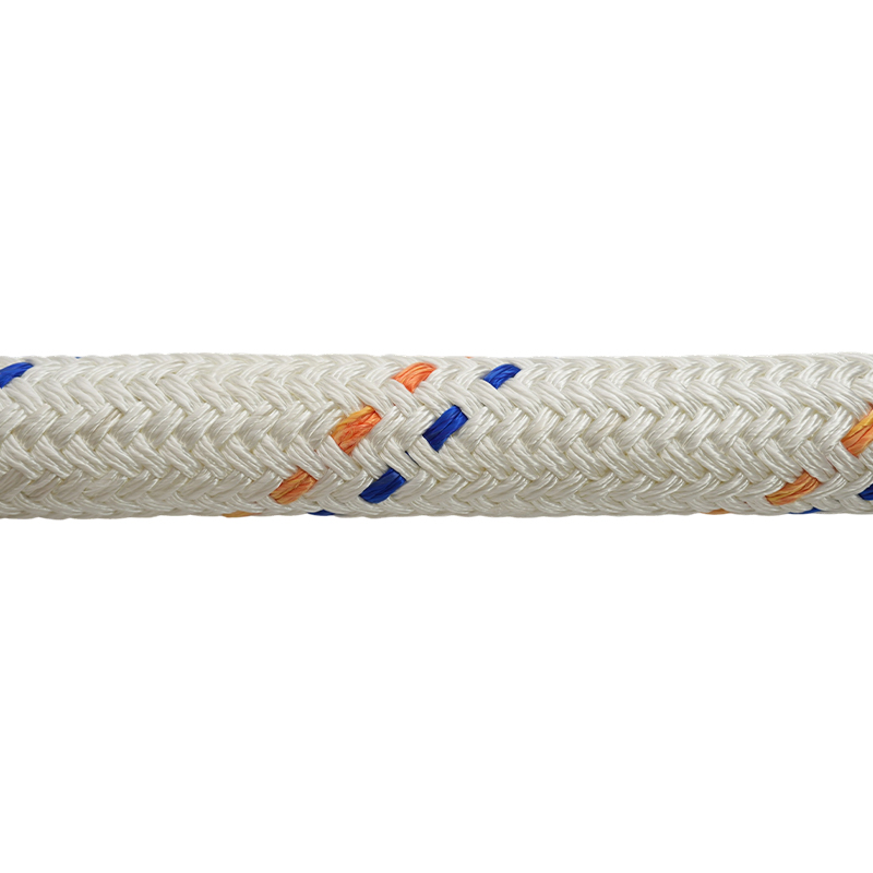
Polypropylene Multi-filament Mooring Tail
-
 View More
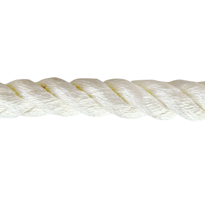
3-Strand Polyester Mooring Rope / Line
-
 View More
8-Strand Polyester Hawser Mooring Rope / Line
-
 View More
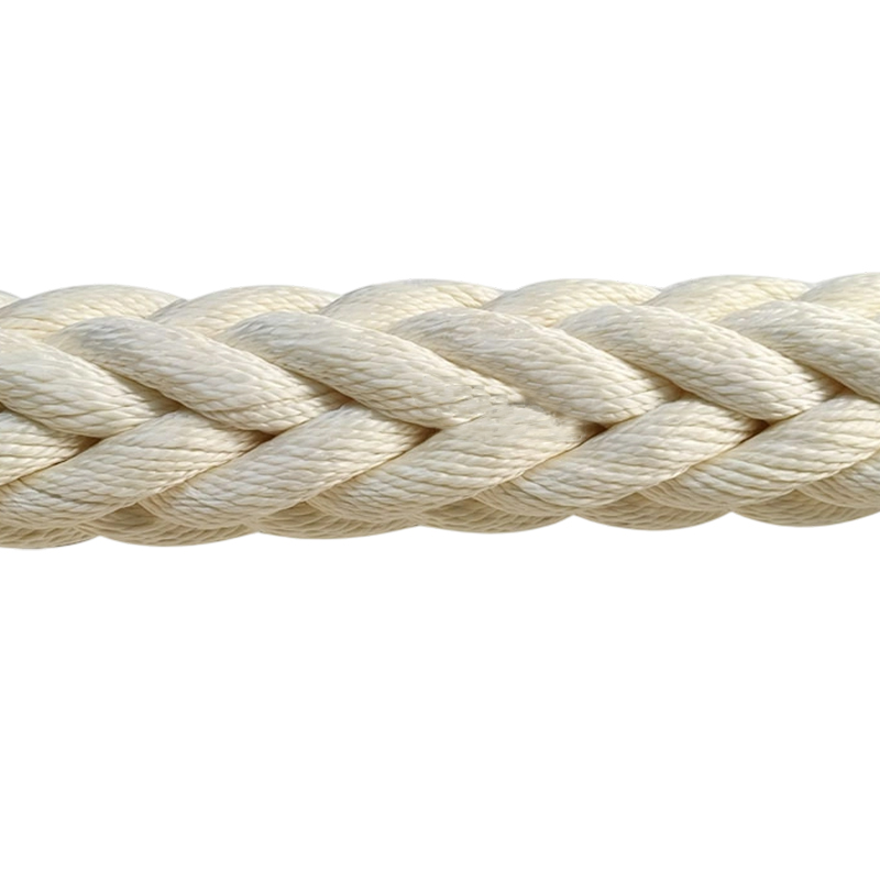
12-Strand Polyester Mooring Rope / Line,Hawser
-
 View More
Polyester Double Braided Hawser Mooring Rope / Line